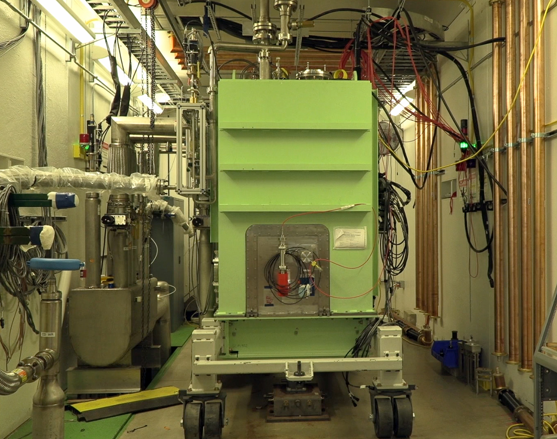
FRIB uses superconducting radio frequency technology in its linear accelerator to efficiently accelerate heavy ion beams for nuclear physics research.
FRIB’s high-power linac consists of 46 cryomodules (green boxes) of six different types. The cryomodules contain superconducting radio frequency (SRF) resonators and superconducting solenoid magnets. Operating at cryogenic temperatures of 2 kelvin (K) and 4.5 K, the SRF resonators accelerate the beam with high voltage (> 1 million volts) while the solenoids steer and focus it. Using its state-of-the-art cleanroom, FRIB staff processed and tested 324 superconducting resonators of four different types. The four different SRF resonator types are specially tuned to accelerate to different speeds, each faster than the last. The team then assembled them into 46 cold-mass groups for installation in cryomodules. At peak, the team delivered nine cryomodules every six months, utilizing five assembly bays and on-site testing.
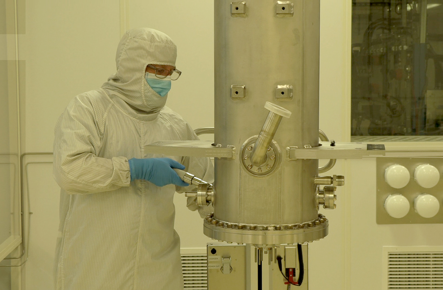
Inspection
The inspection team makes use of a variety of resources, including state-of-the-art metrology equipment and a borescope system. A coordinate measurement machine (CMM) is used for dimensional checks for all FRIB production resonators. Borescope inspection of the resonator interior is done after bulk etching. The CMM features a fully indexable and rotatable probing system, an automatic tool change rack, and a CAD interface. The CMM measurement volume is 1.2m × 2.2m × 1m, allowing parts large and small to be measured at high speeds with excellent precision and accuracy. Other state-of-the-art equipment includes portable CMM arms, laser trackers, and digital height gauges.
Chemical-processing facilities
Chemical-etching facility
The chemical-etching facility is used for buffered chemical polishing (BCP) of niobium. The etching is done inside chemical fume hoods for safety. BCP is done in a class 1000 clean environment. One hood is dedicated to acid storage, the second for resonator etching, and the third for part etching. The facility is adjacent to the cleanroom complex. After etching and rinsing with ultra-pure water, resonators are transferred to the clean room via a pass-through.
Electropolishing facility
FRIB is constructing and commissioning an electropolishing (EP) process. The process is being designed with flexibility to accommodate various resonator types (QWR, HWR, and elliptical resonators). This EP system can do conventional EP and cold EP. Currently, fixturing is designed to process multi- and single-cell elliptical resonators and FRIB β=0.53 half-wave resonator resonators.
Cryomodule test facility
Cryomodule certification
All FRIB cryomodules are tested before installation into the FRIB linear accelerator. The tests are performed in a bunker for radiation shielding. Testing is done at cryogenic temperatures with radio frequency (RF) drive power up to 8 kilowatts. During FRIB production, two cryomodule test bunkers were used, one in the east highbay and the other in the Superconducting Radio Frequency (SRF) Highbay. During the test, staff measures the accelerating voltage, checks for multipacting barriers and field emission, and locks the RF amplitude and phase.
Resonator certification
All FRIB resonators are tested before installation into a cryomodule. Testing is performed at cryogenic temperatures with low RF drive power (up to about 100 watts). Resonators with helium jackets can be cooled down and quickly, using the Dewar to provide insulating vacuum. With two Dewars, up to five resonators per week can be tested during peak resonator production for FRIB. During the test, staff measures the quality factor as a function of accelerating voltage, conditions multipacting barriers, and checks for field emission.
Vacuum furnace
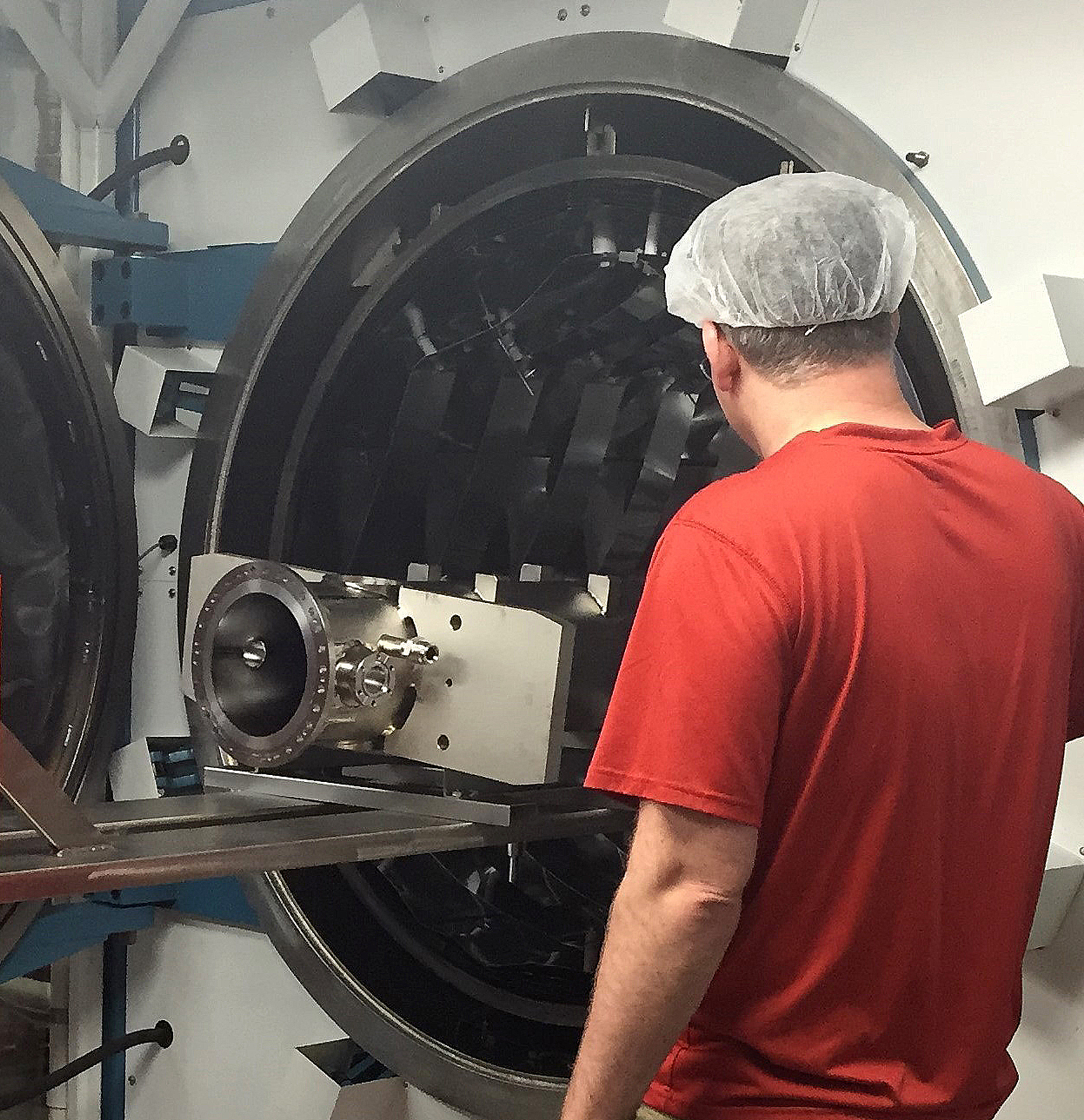
Once a resonator has completed a bulk chemical-etch process, it is then degreased and completely dried before being moved into the vacuum furnace area that is located in a clean zone (class 1000 clean room). The resonator is then loaded into the vacuum furnace chamber.
All FRIB resonators are fired in the high-temperature vacuum furnace starting with a soak at 350°C for 12 hours and then ramping up to 600°C for 10 hours. The lower temperature is used to avoid annealing and subsequent movement of the quarter-wave resonator inner conductors. Vacuum chamber evacuation is performed by two contaminant-free cryopumps with the chamber pressure settling around 1 × 10⁻⁷ torr. A residual gas analyzer is used to monitor the process and provide a detailed gas analysis of the resonator processing cycle.
The vacuum furnace will be used for nitrogen doping processing in the future resonator research and development program.
The risk of hydrogen Q-disease has been eliminated on FRIB resonators by implementing a hydrogen degassing step after the bulk chemistry process.
Nitrogen doping processing has been developed for future furnace operations.
Furnace usable work hot zone is 24 × 24 × 60 inches (60.96cm × 60.96cm × 152.4cm).
The furnace can support an evenly distributed maximum workload of 750 pounds (326.7 kg).
The furnace is capable of operating temperatures up to 1315°C (2400°F) in vacuum.
The furnace is vacuum evacuated using two cryopumps that do not contribute any contamination to the vacuum chamber since it functions by capturing gases.
Cryopump pumping speed with argon is 8300 liters/second and the capacity (with argon) at 1 × 10⁻⁶ torr is 6000 standard liters.
Typical working vacuum pressures at maximum temperatures will range from high vacuum to 1 torr depending on the outgassing of the workload.
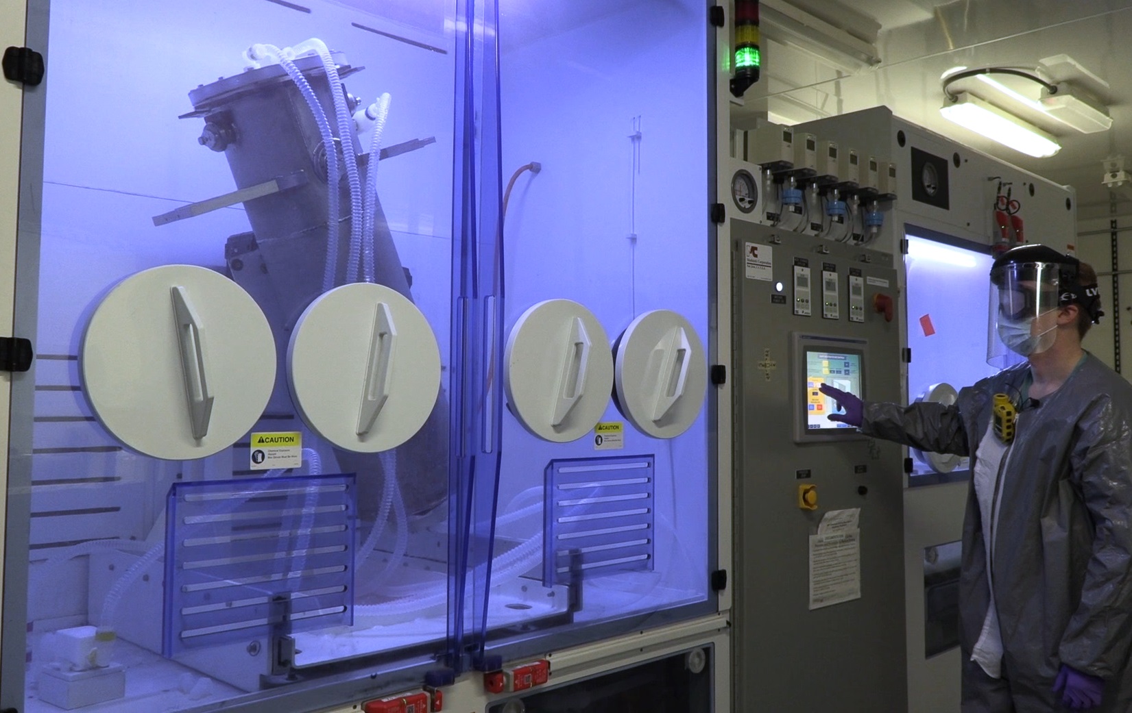
High-pressure rinse systems
Particle-free processing
Chemically processed resonators and degreased superconducting radio frequency (SRF) components are brought into the SRF clean room through a clean room pass-through, where a variety of particle-cleaning processes can occur:
- A handheld medium-pressure UPW rinse spray gun can be utilized as an initial rinse upon entering the clean room.
- A high-frequency ultra-sonic cleaner designed to target small particles.
- High-pressure water-rinsing (HPR) takes place in an environment class 100, with ultra-pure water, in order to make particle-free SRF surface.
- A robotic high-pressure rinse can be programmed to rinse a variety of different geometry resonator types. Parameters such as wand speed, nozzle rotation, and nozzle configuration are to some degree customizable to achieve the best coverage of resonator surfaces with high-pressure water jets.
- A rotational high-pressure rinse is optimized for use with elliptical-style resonators. Parameters such as rotation speed, nozzle traverse speed, and nozzle design are customizable.
- Liquid particle and total organic carbon measurement tools are available as quality-assurance checks for high-pressure rinse processes.
- The HPR’ed resonator is dried in the HPR room.
- The dried resonator is transferred to the resonator assembly area through a cleanroom pass-through.
Manual high-pressure rinse
A handheld spray gun connected to the HPR pump is used to pre-rinse parts and resonators in the clean room pass-through zone before being taken into the ISO 5 clean room to undergo further cleaning and drying.
Robotic high-pressure rinse
An automated robot is used to rinse resonators of various geometries utilizing six axes of rotation on the robot and an additional rotation axis that rotates the resonator. A high-pressure pump outside of the clean room delivers ultra-pure water to the system via flexible plumbing. Ultra-pure water runs through the plumbing to a wand installed to the end of the robot and out of the spray nozzle at the end of the rinse wand. The nozzles can be changed to optimize the spray pattern for each unique resonator type.
Quality assurance
Preliminary resonator cleanliness is assessed using two diagnostic tools: a liquid-particle counter and a total organic carbon (TOC) analyzer. The liquid-particle counter is used to check for the presence of particulate. The TOC analyzer is used to check for the presence of oils or organic growth. These measurements are taken on water samples collected from rinse water out of the resonator at the beginning and end of each process to ensure the system is clean and that the resonator cleanliness has improved over the course of the rinse process.
Rotational high-pressure rinse
A rotational HPR system is installed in the cleanroom, with the goal of rinsing elliptical-style resonators. The resonator is installed to the top of the stand, which has a rotating table to spin the resonator. A wand installed to a linear actuator is used to move the spray nozzle up and down the beamline as the resonator rotates. Water is supplied to the system with a high-pressure rinse pump supplied by the facility ultra-pure water system.
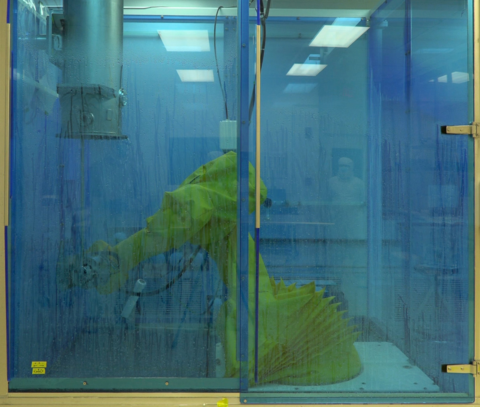
Clean rooms and assembly complex
SRF clean room
FRIB's SRF clean room consists of 15 m2 of ISO 7, 210 m2 of ISO 6, and 100 m2 of ISO 5 floor space. All of the floor space has epoxy-coated concrete floor, with in-wall air returns, and a ceiling height of 3 m. The clean room has type E-1 Lab Grade water available from points of use in the ISO 6, and ISO 7 rooms. The supporting ultra-pure water (18 MΩ/cm) system has storage capacity of 1800 liters (L), with a makeup rate of up to 18 liters/minute. The clean room is equipped with several 225 -kilogram (kg) capacity lift carts, computer work stations, hand tools, ultrasonic cleaners, as well as air, liquid, and surface particle counters.
Clean room prep area
The clean room prep area performs many steps for clean room processing:
- Magnetization measurement and degaussing for parts
- Cold-shocking items
- Salt-soaking items
- Quality-assurance document review
- Visual inspections
- Degreasing and cleaning items with ultrasonic cleaners
Vacuum laboratory
Superconducting linear accelerators require particle-free vacuum systems that can achieve high vacuum. The vacuum lab is able to leverage an ISO 5 clean room area to prepare components that will go on the beam line. To achieve high vacuum, there is a clean oven in the cleanroom that will bake the parts to 260°C to remove water and hydrocarbons.
Superconducting large-gap magnets
Two 120-ton and two 180-ton superconducting dipole magnets both alter the direction of FRIB's fast-moving beam and separate the isotopes in the beam to be studied.
The four large superconducting dipole (SCD) magnets in the fragment preseparator are named SCD1, SCD2, SCD3, and SCD4. The SCD1 and SCD2 magnets are magnetically identical 30° magnets located within the beam-dump vacuum vessel in the FRIB target facility.
The SCD3 and SCD4 magnets are magnetically identical 50° magnets. They are placed along the vertical preseparator that takes the beam from the FRIB linear accelerator (linac) level to ground level.
The SCD3 magnet is the largest magnet in the vertical preseparator. It produces a large magnetic field with little energy input to steer the beam from the FRIB linac (32 feet underground) up toward the ground-level experimental systems.